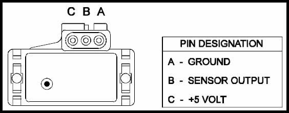
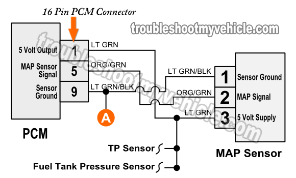
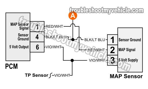
Map Sensor Wiring Diagram. Now if you don't have a vacuum pump, don't worry. All you have to do is connect the main "A" pin to your ECU's power source, the "B" pin to the ground, the "C" pin to the signal wire, and the "D" pin to the return wire. In fuel-injected automotive engines, a manifold absolute pressure (MAP) sensor is used to continuously monitor the amount of air flowing into the engine, so the computer can calculate air density, adjust the amount of fuel to spray into the combustion chamber and adjust the ignition timing. I'll show you how to test it without one. The purpose of a map sensor wiring diagram is to allow anyone who is unfamiliar with electrical engineering to understand the components involved in the system. It also provides a clear and concise way to locate specific parts and connections that may be needed to diagnose and repair problems. The voltage should steadily drop as the vacuum increases. Under the hood, disconnect the MAP sensor from the intake only.
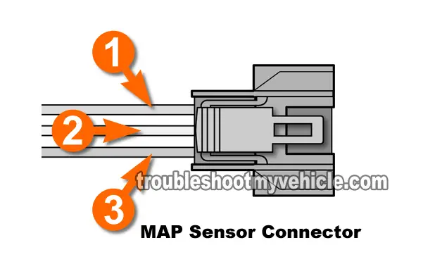
Map Sensor Wiring Diagram. Increase the vacuum on the sensor using the vacuum pump. In fuel-injected automotive engines, a manifold absolute pressure (MAP) sensor is used to continuously monitor the amount of air flowing into the engine, so the computer can calculate air density, adjust the amount of fuel to spray into the combustion chamber and adjust the ignition timing. A MAP sensor tells your MicroSquirt® controller the intake vacuum (or boost) the engine has, which uses this to scale the amount of fuel that is injected. A three-wire MAP sensor has three wires in one connector, power, ground, and signal, which are listed below. The map sensor wiring diagram is a visual guide to the electrical connections that are required for the various electrical components of the engine. Map Sensor Wiring Diagram.
Once you have located the correct wire, you can use the diagram to trace its path to the part you're trying to install or replace.
All you have to do is connect the main "A" pin to your ECU's power source, the "B" pin to the ground, the "C" pin to the signal wire, and the "D" pin to the return wire.
Map Sensor Wiring Diagram. It also provides a clear and concise way to locate specific parts and connections that may be needed to diagnose and repair problems. It is an invaluable resource for those trying. These components include the map sensors, fuel injectors, ignition system, air intake system, and the throttle body. A map sensor monitors and adjusts the air-fuel ratio in an internal combustion engine, making sure it is efficient and performing at its best. The MAP sensor needs power and Ground to create a MAP signal.
Map Sensor Wiring Diagram.


