Map Sensor Wiring. The color of wires will vary and are color-coded depending upon the brand of the sensor. Depending on the type of sensor you have, connecting the wiring may be as easy as plugging the existing wire into the new sensor. This is necessary as you need to wire the sensor into the power source of the old MAP sensor. When removing the old MAP sensor make sure you know which wire is the signal wire. The MAP sensor is usually found in the engine compartment mounted to the intake manifold or firewall. In this powerful guide, we will be more general than specific. This can include wiring problems, intake manifold vacuum leaks, a leaking MAP sensor vacuum hos,e or even a faulty PCM. Connect another wire to the MAP sensor's ground terminal and attach it to a nearby ground source, such as the engine block.
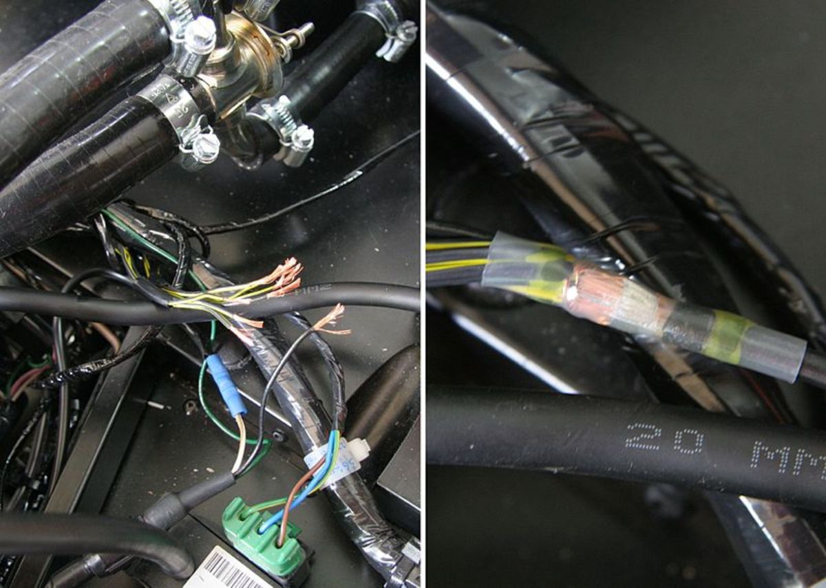
Map Sensor Wiring. Use shielded/grounded cable that is supplied for wiring crankshaft and camshaft signals. The analog MAP sensor can be tested using a digital multimeter (DMM). Install the main power and ground directly to the battery. Connect your vacuum pump to the MAP sensor's vacuum port using a vacuum hose. With your multimeter in Volts DC mode probe the VIO/BRN wire of the MAP sensor connector. Map Sensor Wiring.
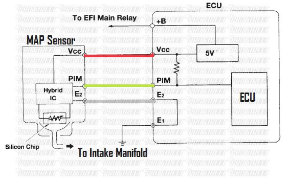
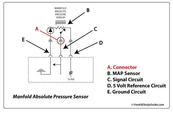
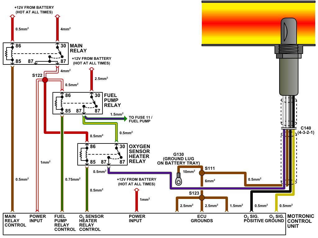
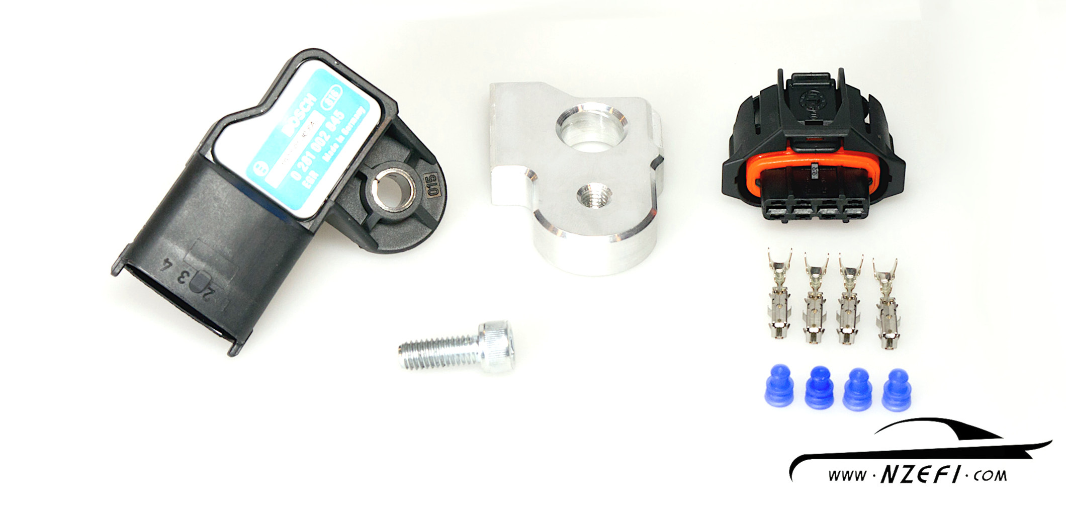
This means that it has a power wire, a Ground wire and a signal wire.
With your multimeter in Volts DC mode probe the VIO/BRN wire of the MAP sensor connector.

2015 67 Powerstroke Map Sensor Location
Bosch Map Sensor Wiring Diagram – Wiring Schema

Honda Map Sensor Wiring Diagram Collection – Wiring Diagram Sample
Map Sensor Wiring Diagram – 4K Wallpapers Review
MAP Sensor Symptoms – Signal Testing – Engine Performance
Toyota supra map sensor wiring
92 Honda civic map sensor wiring
melati: [23+] Jo 1mdw Wiring Diagram, Sensor MAP VW 2.5L Cableado Y …
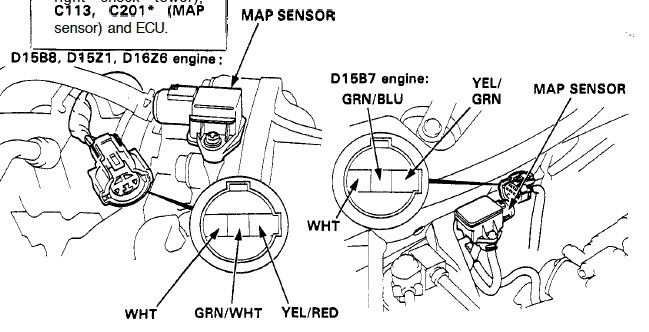
Honda Map Sensor Wiring Diagram – Wiring Diagram

P0068 – Manifold absolute pressure (MAP) sensor/mass air flow (MAF …
Bosch Map Sensor Wiring Diagram – Wiring Diagram
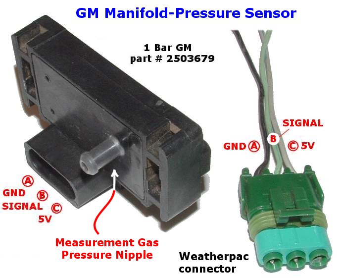
Using a GM MAP Sensor for Measuring Manifold Pressure (Tech Edge)
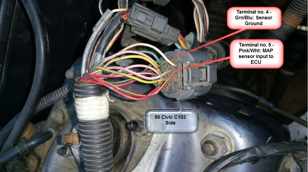
Map Sensor Wiring. When issues emerge, the vacuum hose is most likely to blame. Each wire has a color-coded label that identifies it. This is necessary as you need to wire the sensor into the power source of the old MAP sensor. The color of wires will vary and are color-coded depending upon the brand of the sensor. Default; In Stock; Using the Honda Map Sensor Wiring Diagram is simple.
Map Sensor Wiring.